Penarth Dock, South Wales - the heritage & legacy . . . |
Penarth Dock, South Wales - the heritage & legacy . . . |
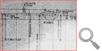
Volume Three - The Pontoon Era - The plant specification, pumping plan and operation of the pontoon . . . There is a slight contradiction in the specification of the pumps since the quotations and pumping plan clearly indicate four conventional centrifugal pumps are included. The report of “The Engineer” in September 1909 also confirms that “four centrifugal pumps and engines for working same, manufactured by Gwynnes Limited of the Hammersmith Ironworks, S.W” were supplied, but then, in a later paragraph states that “A duplex reciprocating pump, with a capacity of 100 tons per hour, has been supplied by Henry Watson and Sons of Walker Gate (Newcastle) . . . . etc.” I could find no record of the supply of this pump, nor can I see this pump in any drawing, and since there are two independent pumping systems clearly one pump could not serve both systems. I conclude, therefore, that the pumping arrangement has been inaccurately reported by “The Engineer” on this occasion. Pumping Plan
Operation of the pontoon The control room for the pontoon was the valve room situated on top of the wall half way along the floating dock and which straddled the lateral split line of the self docking feature described earlier. From the pumping plan it is clear that the valves controlling the flow of water to and from the floatation chambers were connected to a series of hand levers probably similar to those which operated points and signals in a railway signal box. A system of levers connected each of the 26 chamber control valves to a central control point which allowed the pontoon master to control the trim of the pontoon as it raised its load, the ship. out of the water. |
|||||
| Introduction | |||||
| Contents | |||||
| Search this site | |||||
| Contributions | |||||
| Links | |||||
| Recent Updates | |||||
|
|||||
| | volume 03 | chapter 07 | page 05 | << previous page << | index to volume three | >> next page >> | | |||||