Penarth Dock, South Wales - the heritage & legacy . . . |
Penarth Dock, South Wales - the heritage & legacy . . . |
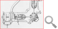
Volume Three - The Pontoon Era - The plant specification, pumping plan and operation of the pontoon . . . We sincerely hope and strongly recommend that we should be allowed to fit our usual type of piston valve for an engine of this pressure and not a slide valve. The latter is liable to give trouble and we cannot recommend it, while the former type we can recommend in every way. The extra stroke of engine and the fact of the pistons being forged will increase the cost of each engine by Twenty Pounds £20. 0. 0.” The pumps are driven by the engines by way of vertical shafting with flexible couplings and the underside of the coupling with a ball race with balls of no less than 1” diameter, presumably a thrust bearing to support the weight of the drive shaft. Also plummer blocks will be supplied with the necessary long, gunmetal bearings. With regard to the shafting we should not recommend the steel pins to have rubber and canvas composition sleeves as we do not think they would last any time. We would propose that these should be made of leather.” The coupling at the upper end of the drive shaft “to be of special form and equipped with extra large steel pins to connect the crankshaft and allow for vertical movement.” The engines for the Kobe installation ran at 270 r.p.m. and speed control was effected by a Pickering governor situated between the gun metal stop valve and the valve chest which was driven by a belt from the engine shaft. The high pressure valve received steam at the centre, exhausting over the outer edges, the steam being conveyed to the low pressure cylinder by a copper pipe. The low pressure valve received steam at the outer edges and exhausts from the centre into the atmosphere through an exhaust head. |
|||
| Introduction | |||
| Contents | |||
| Search this site | |||
| Contributions | |||
| Links | |||
| Recent Updates | |||
|
|||
| | volume 03 | chapter 07 | page 03 | << previous page << | index to volume three | >> next page >> | | |||